4

Model:REF(Flange Type)、RET(Thread Type)
 

 Product accent:
  • Valve Body is made by Stainless Steel #316, suitable for fluid, air and vapor.
  • The gate is balanced-pressure designed, which will not influence the outlet pressure caused by unstable inlet pressure.
  • When the outlet pressure responds directly to the pressure control chamber and adjusts the setting pressure, it responds quickly and adjusts the pressure accurately.
  • Design of piston and diaphragm improves the inability of sustaining pressure and leakage.
  • Pressure Adjusting Range:
    (1 kgf/cm2 = 14.2 psi)
    1.5kgf / cm2∼6kgf / cm2
    4kgf / cm2∼10kgf / cm2
    8kgf / cm2∼13kgf / cm2
  • Applied Temperature:
    -15℃∼80℃
  • Valve Body Testing Pressure :35 kgf/cm2
  • Please cover steam pipelines with thermal materials
  • Special order can be arranged for higher pressure adjustment range

Thread Type-illustration
  1. Pressure Gauge:(依流體選用)
  2. Upper Cover:Stainless Steel 316
  3. U-ring:NBR / Viton
  4. Piston:Stainless Steel 316
  5. Sealing Spacer:NBR / Viton/Teflon
  6. Shaft:Stainless Steel 316
  7. Main Body:Stainless Steel 316
  8. Diaphragm:NBR / Viton
  9. HU-ring:NBR / Viton
  10. Spring:Spring Steel
  11. Lower Cover:Stainless Steel 316
  12. Washer :Brass
  13. Adjusting Stem:Stainless Steeel 304
Item No Thread Type H L CV
RET-15S 1/2" 75 71 2.5
RET-20S 3/4" 75 86 4.0
RET-25S 1" 81 90 6.5
RET-40S 1 1/2" 115 115 13.0
RET-50S 2" 115 120 17.0

尺寸單位:mm


Flange Type-illustration

  1. Pressure Gauge:(依流體選用)
  2. Upper Cover:Stainless Steel
  3. O-ring:NBR / Viton
  4. U-ring:NBR / Viton
  5. Piston:Stainless Steel 316
  6. Sealing Spacer:NBR / Viton
  7. Shaft:Stainless Steel 316
  8. Diaphragm:NBR / Viton
  9. Main Body:Stainless Steel 316
  10. UH-ring:NBR / VIiton
  11. Fixed Bolt:Stainless Steel 304
  12. Spring:Spring Steel
  13. Lower Cover:Stainless Steel 316
  14. Washer:Brass
  15. Adjusting Stem:Stainless Steel 304
Item No Flange Type H L CV
REF-15-S 1/2" 75 150 2.5
REF-20-S 3/4" 82 153 4.0
REF-25-S 1" 82 153 6.5
REF-40-S 1 1/4" 115 190 13.0
REF-40-S 1 1/2" 115 190 13.0
REF-50-S 2" 115 192 17.0
REF-65-S 2 1/2" 185 210 30.0
REF-80-S 3" 185 225 42.0
REF-100-S 4" 230 250 75.0
REF-150-S 6" 290 310 170.0

 尺寸單位:mm


Applied Condition of Direct-activated Pressure Reducing Valve

  • Installing pressure reducing valve directly in the sub-pipe can reduce fluid pressure inside the pipe.
  • Installing a filter in the inlet of pressure reducing valve can prevent block of valve gate caused by impurities and limescale.
  • Installing pressure relief valve downstream pressure reducing valve can protect the system.
  • While using screws to connect pressure reducing valve, joints should be installed in the inlet and outlet to make maintenance easy.

Pressure Setting and Flow Rate of Direct-activated Pressure Reducing Valve

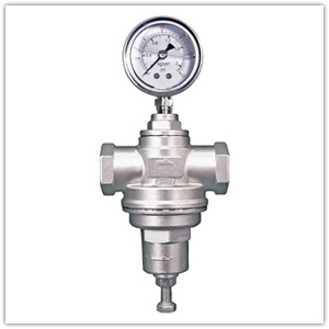
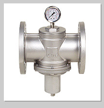
Direct-activated pressure reducing valve directly opens and closes the valve gate by the outlet pressure. When outlet pressure is under setting pressure, valve gate automatically opens. To make valve gate fully open, adjustable pressure range and setting pressure are relative points.

A: Pressure drop needed for fully-opened valve gate = , B=Adjustable Pressure Range Maximum – Minimum
B:Adjustable Pressure Range (=Maximum Minimum Adjustable Pressure Range)
C:Setting Pressure of Outlet
D:Pressure of fully-opened outlet valve gate, P=C-A

Example:
Pressure drop needed for fully-opened valve gate for adjusting pressure range 3~9 kgf/cm2 of direct-activated pressure reducing valve.

If the setting pressure of outlet is 6kgf / cm2, pressure of fully-opened valve gate will be P=6-1.5=4.5 kgf/ cm2(Outlet pressure should go down under 4.5kgf/ cm2 to make valve gate fully open)


Flow Chart of Direct-activated Pressure Reducing Valve


Z-Tide Valves Industrial Co.,Ltd     
       TEL:(02)2999-8885•FAX:(02)2999-7456•E-mail: zt.valve@msa.hinet.net 
 Official Exporting Department :    Elite Line Industrial Corporation
上海地區銷售代理商 上海僑鼎閥門有限公司
We reserve the right to change the specifications listed in catalogues and the website without notice. c 2008 Z-Tide Valves All Rights Reserved.